Most engineers know concrete cracks, so they reduce the stiffness in the model. Then a lot of them do the same thing: pick one number, often 0.35, and apply it to everything. Beams, columns, walls, slabs, all cracked by the same factor. It feels consistent. It's actually one of the quieter ways to get a load path wrong, because the whole point of cracked-section modifiers is that different elements crack differently, and giving them all one value erases exactly the difference that governs where the load goes.
Why the values differ in the first place
The standard cracked-section values aren't arbitrary. They encode how much each element type actually cracks under its own loading:
| Element | Typical modifier | Why |
|---|---|---|
| Columns | 0.70 Ig | Axial compression suppresses cracking, so most stiffness survives |
| Walls, uncracked | 0.70 Ig | Same logic, until in-plane stress cracks them |
| Walls, cracked | 0.35 Ig | Once in-plane bending cracks the section, stiffness halves |
| Beams | 0.35 Ig | Flexural elements crack extensively |
| Flat slabs | 0.25 Ig | Thin, flexural, crack the most |
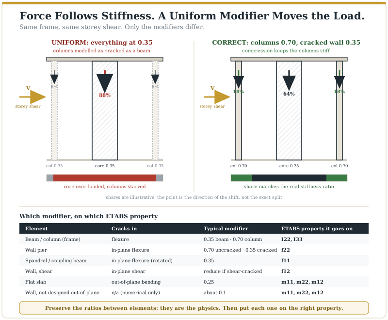
Read the pattern. A column keeps twice the stiffness of a beam because compression holds the cracks shut. A slab keeps a third of what a column keeps. These ratios are the engineering. Apply 0.35 to all of them and you've told the model that a compressed column is as cracked as a flexural beam, and that a thin slab is as stiff as a wall.
Force follows stiffness, so uniform modifiers move the load
Lateral force distributes in proportion to relative stiffness. That's the mechanism the uniform value breaks.
Give a core wall and a perimeter column the same 0.35 and you've preserved the wrong ratio between them. The columns, which should have kept 0.70, are now modelled far softer than they are, so the model sends them less load and the core more. Leave the slab at full stiffness while cracking the beams and you've done the reverse for the floor system: the model routes moment through an artificially stiff slab that in reality has cracked most. Either way, load migrates toward whatever you accidentally left stiff. The storey stiffness reports become unreliable, the torsional response shifts because the stiffness balance across the plan is wrong, and the drift is computed on a stiffness distribution the real building doesn't have.
None of this throws a warning. Every member passes its own check against forces that were never going to arrive.
It's not just the value, it's which property you put it on
This is the second half of the mistake, and CSI's own guidance is explicit about it. Each element cracks in a specific direction, and ETABS has a separate modifier for each:
- Frames (beams, columns): the flexural modifier goes on I22 and I33.
- Wall piers: flexure is in-plane, so the EI modifier belongs on f22 (local axis 2 is vertical by default). Spandrels are rotated, so theirs goes on f11. Put it on the wrong one and it hardly affects anything.
- Shear in walls: a separate decision on f12, as covered in the F12 post.
- Slabs: bending is out-of-plane, so cracking has to go on m11, m22 and m12. Reducing f11/f22 on a slab does nothing for its bending.
- Walls not designed for out-of-plane bending: m11/m22/m12 dropped to about 0.1 to avoid numerical instability, not to represent cracking.
"Apply 0.35 to the wall" is not a complete instruction. Applied to the wrong property it changes nothing; applied to every property it softens directions that were never cracked.
One model can't serve two purposes
A final trap in the uniform habit. Serviceability drift checks and ultimate strength design want different stiffness assumptions. Practice in tall-building work often keeps a stiffer model (around 0.70) for drift and a more cracked one (around 0.35) for design forces, because the cracking state at service wind is not the cracking state at ultimate. One number applied to one model for both jobs is wrong for at least one of them.
What this means in practice
Set modifiers by element type, by direction, and by limit state, not by habit:
- Assign by element: columns and uncracked walls higher, beams and cracked walls lower, slabs lowest. Preserve the ratios; they're the physics.
- Assign by property: I22/I33 for frames, f22 for piers, f11 for spandrels, m11/m22/m12 for slabs, f12 for wall shear.
- Check what's cracked: compare wall stresses against the cracking threshold and reduce only where it's exceeded, rather than blanket-reducing.
- Separate service and ultimate where the drift and strength checks need different stiffness.
The uniform value looks like consistency. It's actually a decision to ignore the one thing the modifiers exist to capture: that a column, a beam, a wall and a slab do not crack alike. Get the ratios right and the load path is honest. Flatten them and the model quietly sends the load somewhere the real building won't.
The above reflects general modelling practice for educational purposes; modifier selection on any specific project remains a matter of engineering judgement against the relevant standards.